MODEL REFERENCE
CASIO XJ-UT312WN
15 errors · 18 troubleshooting topics · 110 guides

The checks and guides below come from the official manuals for this model.
No matches for this wording. Try a light name, error code or a shorter phrase.
Errors and indicators
Light patterns and messages documented in the manualFind the indicator lights
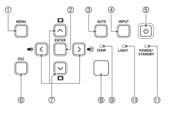
Diagram key
- 1: MENU opens or closes settings.
- 2: ENTER confirms a selection.
- 3: AUTO automatically adjusts RGB frequency and phase.
- 4: INPUT selects the source.
- 5: ON/Stand-by power key.
- 6: ESC cancels or exits.
- 7: Four cursor keys Up, Down, Left, Right for menu navigation and supported adjustment.
- 8: Illuminance sensor used when automatic brightness sensing is enabled.
- 9: TEMP temperature indicator.
- 10: LIGHT light-source indicator.
- 11: POWER/STANDBY power indicator.
- Up/Down trapezoid symbols: With no menu/dialog, these keys open keystone adjustment; Up/Down adjusts vertical and Left/Right horizontal distortion.
- Left/Right light symbols: With no menu/dialog and Light Control On, these keys change light output.
内部が高温になっています。設置状況を確認してください。high internal-temperature warning2 checks
内部が高温になっています。電源をオフにします。high temperature automatic shutdown2 checks
POWER steady red / LIGHT steady red / TEMP steady redfan fault
The fan is abnormal and power shut down automatically.: POWER steady red / LIGHT steady red / TEMP steady red. If an error caused shutdown, wait for the fan to stop before removing the cord. Unplugging during fan rotation can prevent recovery. Confirm POWER is steady red and the fan has stopped. Unplug; after the indicators go out wait a while, reconnect and turn on. If it recurs contact the repair enquiry service or dealer.
POWER steady red / LIGHT unspecified / TEMP steady redsystem fault or other malfunction
A system fault or external noise caused malfunction and automatic shutdown.: POWER steady red / LIGHT unspecified / TEMP steady red. If an error caused shutdown, wait for the fan to stop before removing the cord. Unplugging during fan rotation can prevent recovery. Confirm POWER is steady red and the fan has stopped. Unplug; after the indicators go out wait a while, reconnect and turn on. If it recurs contact the repair enquiry service or dealer.
POWER steady red / LIGHT red flashing about1second / TEMP red flashing about1secondlight-source unit fault
The light-source unit went out or failed to light and power shut down automatically.: POWER steady red / LIGHT red flashing about1second / TEMP red flashing about1second. If an error caused shutdown, wait for the fan to stop before removing the cord. Unplugging during fan rotation can prevent recovery. Confirm POWER is steady red and the fan has stopped. Unplug; after the indicators go out wait a while, reconnect and turn on. If it recurs contact the repair enquiry service or dealer.
POWER steady red / LIGHT off or flashing red / TEMP red flashing about2secondsmemory fault
An internal memory error caused automatic shutdown.: POWER steady red / LIGHT off or flashing red / TEMP red flashing about2seconds. If an error caused shutdown, wait for the fan to stop before removing the cord. Unplugging during fan rotation can prevent recovery. Confirm POWER is steady red and the fan has stopped. Unplug; after the indicators go out wait a while, reconnect and turn on. If it recurs contact the repair enquiry service or dealer.
ID-01flash Loader: Firmware file format problem
Firmware file format problem: Download the correct exact-model firmware again, then repeat the update.
ID-02flash Loader: Cannot establish a projector connection
Cannot establish a projector connection: Check that the USB driver is installed, the USB cable is correctly connected and projector power is on. The message also instructs checking USB, turning projector off and on, then retrying.
ID-03flash Loader: The ROM version is not newer
The ROM version is not newer: The downloaded firmware is the same version as or older than the installed version. Update only with a newer version.
ID-04flash Loader: ROM data is for another model
ROM data is for another model: Use the correct exact-model firmware file.
ID-01lOGO Loader: Logo header file format problem
Logo header file format problem: Download the correct exact-model header again, then repeat transfer.
ID-02lOGO Loader: Cannot establish a projector connection
Cannot establish a projector connection: Check the USB driver installation, cable connection and projector power. The message also instructs checking USB, turning projector off and on, then retrying.
ID-04lOGO Loader: Logo header is for another model
Logo header is for another model: Use the correct exact-model .cph header.
ID-05lOGO Loader: Logo image has too many pixels
Logo image has too many pixels: Reduce the image size within640×480–1280×800 and retry.
ID-06lOGO Loader: Image file type is unsupported
Image file type is unsupported: Use a BMP in RGB24-bit full colour.
Troubleshooting
Find the problem you are experiencingMissing picture dots are not necessarily a faultView
Some non-illuminating picture dots can occur despite precision manufacturing; the manual says this is not a fault.
Image discolouration after impact4 steps
- Avoid shocks during projection.
- If an impact interrupts or discolours the picture, use INPUT to reselect the previously projected source.
- If it does not recover, turn off and on again.
- If there is an error, follow the reviewed indicator/error table.
Blur after condensation3 steps
- Sudden cold-to-warm movement or rapid room heating can cause condensation on the lens or inside.
- Turn off, leave for a while, then turn on again.
- No fixed waiting time is specified.
Power will not turn on2 checks
- POWER indicator is not lit
- Connect the power cord correctly.
- TEMP or LIGHT continues lit or flashing
- Check the reviewed error-indicator table.
No picture or abnormal projection3 checks
- Source is off or not sending a signal
- Confirm the connected computer/video device is on and working.
- Wrong input source
- Select the source matching the connected equipment.
- Component source may be incompatible
- Try connecting the source composite-video output to VIDEO instead.
Severely wrong picture colour or position1 check
- RGB/component mode does not match input
- In Input Settings > COMPUTER1 Terminal or COMPUTER2 Terminal, matching the connected port, choose RGB or Component for the signal, or Auto.
No sound4 checks
- Projector volume is too low or muted
- Use VOLUME+ or VOLUME− to adjust and unmute.
- Source volume is low or absent
- Adjust the source equipment volume.
- Audio is connected to the wrong assigned input
- Check the assigned audio-input port for the current source using the reviewed audio-input instructions.
- Audio Output is Line
- Change Device Settings2 > Audio Output to Speaker.
Incorrect picture colours3 checks
- Brightness may not suit input
- Press FUNC, choose Brightness and adjust it.
- Colour mode may not suit input
- Press FUNC, choose Colour Mode and change it.
- Colour balance may not suit input
- Adjust Image Adjustment1 > Colour Balance.
Blurred text3 checks
- Focus is wrong
- Slide the focus lever up/down to focus.
- RGB frequency or phase may not match
- For RGB only press AUTO to adjust.
- RGB tracking/phase still needs adjustment
- For RGB only adjust Image Adjustment2 > Frequency and Phase.
Cannot pass the power-on password prompt1 check
- Power On Password is enabled
- Enter the correct password and ENTER. If remote keys cannot enter it, use the reviewed remote-control troubleshooting checks.
Remote control does not work3 checks
- Batteries exhausted
- Replace the remote batteries.
- Outside control range
- Operate within approximately5m of the projector.
- IDs do not match
- Match remote and projector IDs or set either to All.
TEMP or LIGHT remains lit or flashing1 check
- An error may have occurred
- Consult the reviewed error-indicator table; do not interpret it solely by table row order.
Light-source unit does not light2 checks
- BLANK temporarily switched the light off
- Press BLANK or ESC.
- Light-source unit is at end of life or faulty
- Ask the repair service or dealer to replace it; do not attempt internal replacement.
Unexpected shutdown and restart1 check
- Occasional self-check restart
- A rare automatic self-check restart is not a fault; continue use. If repeated continuously, contact the repair service or dealer.
General abnormal operation recovery1 check
- An abnormality may clear after the stated power reset
- Unplug and leave for at least10minutes.
- Reconnect and turn on.
- If normal operation does not return contact the repair enquiry service or dealer.
- After an error wait for the fan to stop before unplugging.
OCC download fails in a browser1 check
- Browser download limitation
- Try a different browser to download the OCC file.
Projector-name search fails1 check
- Possible projector DNS-address error
- Contact the network administrator to check the projector’s DNS server address.
Guides
安全上のご注意
Instructions from the manualStop for smoke, abnormal heat or smell4 steps
- Adult supervision is required where children can touch or approach the projector.
- If smoke, unusual smell or abnormal heat occurs, stop use because continuing risks fire or electric shock.
- Unplug the power plug.
- Contact the repair enquiry service or dealer.
Safe placement, ventilation and projection light13 steps
- Place on a firm flat stable surface with unobstructed intake and exhaust.
- Keep at least6cm between the projection-facing side and screen/wall and30cm at other sides; place nothing between the projector and screen.
- Do not enclose it, cover it with cloth, or place it on soft carpet, bedding, towels or seats.
- Lock cart wheels.
- Operate at5–35°C.
- Avoid moisture, dust, kitchen fumes, humidifiers, vibration, heated carpets, direct sun, unstable stands and high shelves.
- Do not put heavy objects on it, stand on it, expose it to water or throw it into fire.
- Do not look into the illuminated lens, intake or exhaust; check nobody is looking before switching on and supervise children.
- Do not block the beam or put magnifying glasses, mirrors, aquariums or other refracting/reflecting objects in it.
- Do not touch the lens.
- Do not touch the hot exhaust or place heat-sensitive plastic near or below it.
- Do not open the cabinet or use flammable-gas sprays inside or around it.
- During a thunderstorm do not touch the mains-connected equipment; unplug before storms.
電源コードについて
Instructions from the manualJapan-only model and electrical scope10 steps
- This reference covers only Japan-domestic XJ-UT312WN in the current Japanese MA2201-F manual.
- Do not use this domestic unit overseas.
- Use100V AC50/60Hz.
- Use the supplied power cord only with this projector and its specified grounded Japan outlet.
- Connect earth before plugging in; disconnect earth only after unplugging.
- Keep the outlet accessible.
- Avoid overloaded outlets and sharing an outlet with other equipment.
- Observe extension-cord current ratings.
- Do not use a bundled cord, place it near heaters or under rugs, trap it, load it, heat, modify, cut, forcibly bend, twist or pull it.
- Never handle the cord or plug with wet hands.
Power-cord care and safe movement8 steps
- Insert the plug fully.
- Unplug after use or for long non-use, holding the plug rather than pulling its cord.
- Before moving, turn off and unplug.
- At least yearly unplug and remove dust around plug blades with a dry cloth or vacuum.
- Do not apply detergent to the cord, especially the plug.
- During and immediately after operation the exhaust area is hot.
- Carry the XJ-UT projector by the two illustrated sides, avoiding the exhaust.
- Keep a separate written record of important settings in case malfunction or repair erases them.
故障時は使用しない
Instructions from the manualStop for faults, liquid ingress or impact damage6 steps
- If operation is abnormal, or water, liquid or foreign objects enter, turn power off, unplug and contact the repair enquiry service or dealer.
- Do the same if it is dropped or damaged.
- Keep liquid containers away.
- Do not open, dismantle or modify the case; internal high voltage can cause shock, burns or injury.
- Ask the service or dealer for internal inspection, adjustment or repair.
- Keep plastic bags away from children.
他の電子機器への影響について
Instructions from the manualPrecautions around medical and precision equipment4 steps
- Follow hospital and airline instructions; do not use where prohibited.
- Electromagnetic emissions can affect instruments.
- Do not operate near precision electronic equipment or equipment handling weak signals.
- People using pacemakers should keep the projector away from their chest; if an abnormality occurs move it away immediately and consult a doctor.
電池について
Instructions from the manualRemote and battery safety9 steps
- Use only the specified batteries with correct polarity.
- Do not recharge, disassemble, short-circuit, heat or burn them; do not mix old/new batteries or different types, or use batteries with exposed wrapping.
- Remove exhausted batteries immediately and remove batteries for long non-use.
- If alkaline-battery fluid gets into an eye, do not rub: rinse immediately with clean water and seek medical treatment.
- Wash fluid from skin or clothes with clean water.
- Replace remote batteries at least yearly regardless of frequency of use.
- Do not disassemble or modify the remote or expose it to water; have it serviced by the dealer or repair service.
- Do not use unapproved battery types, burn, crush, cut, or expose batteries to extreme high/low temperatures or very low pressure, as these risk explosion or flammable-liquid/gas leakage.
- Dispose according to local rules.
その他
Instructions from the manualMagnets, internal cleaning and disposal7 steps
- The projector contains magnets.
- People using pacemakers or other medical electrical equipment should keep it away from that equipment.
- If an abnormality is felt, move away immediately and consult a doctor.
- Keep magnetic cards, tapes, prepaid cards and tickets away.
- Arrange paid internal cleaning at least yearly with the dealer or repair service, preferably before the humid rainy season.
- Accumulated dust can reduce brightness or cause fire or failure.
- Dispose of the projector according to local authority rules without dismantling it.
光源ユニットについて
Instructions from the manualLight-source life and laser precautions8 steps
- Laser/LED light-source life is approximately20, 000hours, depending on individual unit, conditions and settings; this is not a guarantee.
- Warranty ends at the earlier of the product warranty period or6, 000hours.
- If the light stops or becomes markedly dim, ask the repair service or dealer to replace the light-source unit.
- Never dismantle or modify the projector.
- The Japan/non-USA label states Class1 under IEC60825-1: 2014.
- The separate USA Class2 label does not authorize overseas use of this unit.
- Do not use adjustments or procedures outside the manual.
- The projection-light warning is Risk Group2 under IEC62471-5: 2015; do not look into the beam or start power while looking into the lens.
無線アダプターyw-41の使用に関するご注意
Instructions from the manualUse the YW-41 wireless adapter safely10 steps
- Use YW-41 only in Japan; it is certified under Japanese radio law.
- Do not dismantle/modify it or remove its certification label.
- Keep it away from small children.
- Follow hospital/aircraft restrictions and consult a doctor or equipment maker when medical devices may be affected.
- It uses2.4GHz DS-SS/OFDM, with an assumed interference distance about40m.
- Before use, check for local licensed/mobile-identification radio stations.
- If interference occurs, change channel/location or stop use; consult dealer/service if unsure.
- Microwaves, static/radiating equipment, reinforced concrete/steel buildings, large metal furniture, people and room barriers can impair reception.
- Reflections create good/bad locations; moving devices slightly may help.
- Third parties may intercept radio traffic; do not use for confidential or life-critical matters.
その他のご注意
Instructions from the manualStorage, environment and image quality precautions8 steps
- Avoid static-prone locations, extreme temperatures, high humidity, abrupt temperature changes, dust, unstable or tilted surfaces, water, oil fumes, tobacco smoke, salt damage and corrosive gases.
- Keep strong fluorescent light and direct sunlight off the remote receiver.
- Avoid trapping hands below the projector during installation or underside adjustment.
- Continuous24-hour operation or ignoring installation conditions can lead to chargeable repair even within warranty.
- Hot, dusty or smoky conditions shorten optical-engine replacement intervals; ask service about timing and cost.
- Keystone correction compresses the image and can reduce quality.
- Use a square-on placement that minimizes or eliminates correction for the best picture.
- USB power may stop at shutdown or an automatic restart; save connected-device data often.
投映までの操作の流れ
Instructions from the manualQuick-start setup and shutdown12 steps
- Install the two supplied AAA alkaline batteries in the remote, matching the polarity marks.
- Place the projector on a firm desk or stand with enough surrounding clearance and read the safety, use and placement precautions.
- Adjust its installation angle.
- Connect the supplied cord to the projector AC inlet and specified Japan outlet.
- Connect the source equipment and turn the source equipment on.
- Press the projector power key.
- On first use select a language in the initial-language screen.
- Press INPUT to select the source.
- Adjust picture size through placement and use the digital screen shift as needed; slide the focus lever up/down to focus.
- There is no zoom ring.
- Use vertical and horizontal keystone correction and light-output adjustment if needed.
- To finish projecting press the power key.
内容物のご確認
Instructions from the manualCheck supplied items and included wireless adapterView
Supplied items: projector, YT-161 remote, two trial AAA batteries(use alkaline), power cord, RGB cable, XJ-UT cable cover, YW-41 wireless adapter(included specifically with UT312WN), Read Before Use/manual-information sheets and warranty.
各部の名称
Instructions from the manualXJ-UT312WN parts, controls and ports8 steps
- XJ-UT exterior callouts identify the illuminance sensor, control panel, indicators, power key, left exhaust, two intake positions, AC inlet, remote receiver, terminal area, focus lever, security bar and Kensington-compatible lock hole.
- Keep vents clear and avoid the hot exhaust and illuminated lens.
- The panel has MENU, ENTER, AUTO, INPUT, power, ESC and four cursor keys.
- Its three indicators are POWER/STANDBY, LIGHT and TEMP.
- Body Up/Down opens keystone adjustment.
- XJ-UT312WN has one HDMI input, COMPUTER IN1/2, MIC, AUDIO OUT, AUDIO IN1/2, USB-A/DC5V, USB-A, LAN, LOGO Micro-USB TypeB, AUDIO IN R/L, VIDEO, MONITOR OUT and SERIAL.
- The shared drawing’s HDMI2(callout1) belongs only to UT352W/UT352WN and is absent on UT312WN.
- Both TypeA ports are USB hosts; their power limits differ.
設置角度の調節
Instructions from the manualAdjust the three installation feet3 steps
- Turn the one underside front adjustment foot to fine-tune the elevation angle.
- Turn the two underside rear adjustment feet to fine-tune side-to-side tilt.
- Place the projector on a firm level table with adequate clearance.
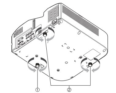
Diagram key
- 1: Turn the one front underside foot to fine-tune elevation. Both rotation directions are retained.
- 2: Turn the two rear underside feet to fine-tune side-to-side tilt. Both repeated foot locations and their rotation arrows are retained.
机上や床への設置について
Instructions from the manualPlace the projector for a square picture7 steps
- Use a firm desk or stand with adequate clearance.
- Aim perpendicular to the screen, with the lens centred.
- A test pattern helps check size, angle, level and focus.
- Keep the plug accessible.
- Leave at least6cm from the projection-facing side to the screen/wall and30cm at other sides.
- Keep the entire projector-to-screen space unobstructed, especially vents.
- If exhaust heat makes the image waver, change air-conditioner airflow or projector position.
パソコンと接続する
Instructions from the manualConnect a computer by HDMI or RGB4 steps
- Use an HDMI cable from source HDMI output to the single projector HDMI input; it carries image and audio.
- For analogue RGB, connect source VGA to COMPUTER IN1 or2 with the15-pin mini D-sub RGB cable.
- Connect source audio to corresponding AUDIO IN1/2 with a stereo-mini cable if sound is required.
- Audio assignments can be changed in Device Settings2.
ビデオ機器と接続する
Instructions from the manualConnect HDMI, component or composite video4 steps
- For HDMI video, use an HDMI cable to the single HDMI input for picture and sound.
- For component video connect Y/Cb/Cr or Y/Pb/Pr to COMPUTER IN1 or COMPUTER IN2 using a mini D-sub-to-component cable.
- Its three plugs are green(Y), blue(Cb/Pb), red(Cr/Pr); use a stereo mini cable to the matching AUDIO IN1/2 for sound.
- For composite video connect the source yellow composite output to VIDEO, and white/red left/right audio outputs to AUDIO IN R/L using the composite video/audio cable.
本機から外部機器に音声出力する
Instructions from the manualConnect amplified external speakers3 steps
- Connect AUDIO OUT to the audio input of amplified speakers or equivalent using a stereo mini cable.
- In MENU > 機器設定2 (Device Settings2) > 音声出力 (Audio Output), choose ライン (Line) rather than the default スピーカー (Speaker).
- Standby audio output is supported through the reviewed Standby RGB/Audio setting.
マイクを接続する(xj-utシリーズ、xj-f21xn、xj-f211wn、 xj-s400un、xj-s400wn)
Instructions from the manualConnect and adjust a dynamic microphoneView
Connect a dynamic microphone to MIC. Plug-in-powered microphones are unsupported. Device Settings2 > Microphone Input Level adjusts0(default, mute) to3(maximum).
Lanケーブルでネットワークに接続する(ネットワークモデルのみ)
Instructions from the manualConnect wired LAN3 steps
- Connect LAN to the network hub/router using Cat5-or-higher cable supporting100BASE-TX/10BASE-T; shielded STP is recommended.
- This supports computer-screen projection and computer setup/control.
- Follow the complete reviewed Network Function Guide.
Logo端子について(ファームウェア更新、ユーザーロゴ転送)
Instructions from the manualConnect the LOGO service port2 steps
- For firmware updating or user-logo transfer connect a computer USB port to the projector LOGO Micro-USB TypeB terminal with a suitable cable.
- Follow the complete separate firmware or logo guide; do not treat this as a USB-host/network input.
無線アダプターを接続する(ネットワークモデルのみ)
Instructions from the manualConnect the wireless adapter and use the cable cover5 steps
- YW-41 can connect to either USB-A/DC5V or USB-A on UT312WN.
- Connect with projector power off, then turn on, as specified by the Network Function Guide.
- The adapter’s separate anti-theft cover fits F/S models only, not XJ-UT.
- Use the projector’s supplied cable cover for adapter protection.
- Keep adapter/covers away from infants.
電子辞書や関数電卓と接続する(ネットワークモデルのみ)
Instructions from the manualProject a supported dictionary or calculator5 steps
- Check CASIO’s verified-compatible models before connection.
- Use the connected device’s manual for its operation.
- Connect a supported electronic dictionary using its specified dedicated USB cable, or calculator using TypeA-to-miniB USB, at either USB-A/DC5V or USB-A.
- Select CASIO USB Tools as input.
- If it does not work, disconnect USB, restart both devices, and reconnect.
ケーブルカバーの取り付けと取り外し(xj-utシリーズ)
Instructions from the manualAttach and remove the cable cover5 steps
- Before fitting or removing the cover, turn off, unplug and wait for cooling if just switched off.
- Turn the projector over and insert cover hooks into the body hook holes.
- Rotate the cover in the illustrated direction to fit it.
- Align the cover screw with its body screw receiver and tighten using a Phillips screwdriver.
- To remove, loosen the screw with a Phillips screwdriver and detach it from the body; separate the screw side of the cover, then withdraw its hooks.
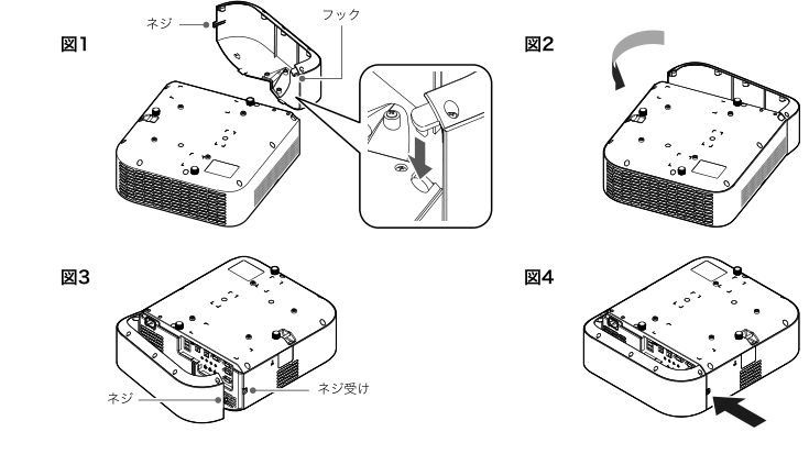
Diagram key
- Figure1 screw: Cover screw; align it with the body receiver in Figure3.
- Figure1 hooks: Cover hooks; insert into the body hook holes. The enlarged inset retains both insertion arrows.
- Figure2 rotation arrow: Rotate the cover in this direction to attach after inserting the hooks.
- Figure3 screw: Align the same cover screw with its receiver.
- Figure3 screw receiver: Body receiver for the cover screw.
- Figure4 arrow: Tighten with a Phillips screwdriver. Removal reverses by loosening and detaching the screw, separating the screw side, then withdrawing the hooks.
リモコンについて
Instructions from the manualUse the supplied YT-161 remote5 steps
- Point the remote at a projector receiver within approximately5m.
- Keep stored remote keys from being held down, because this consumes the batteries.
- Its six grouped callouts identify the emitter, power, ESC, ID/countdown keys1–4, four cursor keys with ENTER, and function keys.
- Power toggles projector power; ESC cancels the current operation; cursor keys navigate and adjust, and ENTER confirms.
- Use the reviewed individual functions for each function key.
電源を入れる、電源を切る
Instructions from the manualTurn power on and off10 steps
- Connect the supplied cord to AC and the Japan outlet.
- Wait until POWER/STANDBY is steady red.
- Press the power key.
- POWER flashes green for a few seconds then becomes steady green and projection begins.
- To turn off press the power key.
- POWER flashes red for a few seconds then becomes steady red.
- Unplug from the outlet.
- After an error always wait for the fans to stop before removing the cord.
- Direct Power On in Device Settings1 starts automatically when mains is connected; default is Off.
- Normal Auto Power Off is10minutes without input/key activity; settings allow5/10/15/20/30minutes or Off.
入力ソースを選ぶ(input)
Instructions from the manualSelect the input source7 steps
- XJ-UT312WN sources are Computer1/2(RGB/component), Video, HDMI, CASIO USB Tools, Network and Templates.
- Native projection is1280×800; matching computer output avoids coarse images, blurred text or moiré.
- Real aspect gives dot-for-dot display.
- Press INPUT, choose the source with INPUT or Up/Down, and ENTER.
- Alternatively wait about3seconds for the selected source to activate.
- Its name appears briefly at upper right.
- A missing signal produces the no-input message.
入力ソースを自動検索する
Instructions from the manualSearch automatically for an input signal8 steps
- Hold INPUT until the searching message appears.
- Once input is found, projection begins and search ends.
- INPUT or ESC stops search.
- Without a signal it searches twice then displays the no-input message.
- UT312WN search order is Computer1, Computer2, Video, HDMI, CASIO USB Tools, Network, Templates, then repeats.
- At startup it begins with the last selected source, but CASIO USB Tools/Network/Templates are not searched at startup; if one was last selected, it starts hardware-input search.
- A No Signal Test Pattern disables automatic search.
- Input Settings > Automatic Input Search can disable it.
映像入力と音声入力の関係について
Instructions from the manualAssign audio inputs6 steps
- Default Computer1/2 audio comes from AUDIO IN1/2; Video from AUDIO IN R/L; HDMI from HDMI.
- CASIO USB Tools and Templates use AUDIO IN1; Network uses network audio via LAN or YW-41.
- Press MENU > Device Settings2 > Audio Input > ENTER.
- Choose a source with Up/Down and assign an audio port with Left/Right.
- Repeat as needed, then MENU to close.
- Device Settings2 Reset restores all items in that menu, not only audio assignments.
オートプロジェクションオフを利用する
Instructions from the manualUse Auto Projection Off8 steps
- Enable オートプロジェクションオフ in Screen Settings; it is disabled by default.
- After previously projecting, no input signal for about5seconds produces a warning; after about another5seconds light and audio switch off.
- Audio presence alone does not prevent it.
- Signal returning on the same source or any key operation restores the light within20minutes.
- After20minutes with light off the projector shuts down automatically, regardless of the normal Auto Power Off setting.
- POWER slowly flashes green while the light is off.
- USB power continues until the projector turns off.
- It does not operate before any signal has been projected, during Templates, countdown or Test Pattern, or during automatic source search.
投映映像と音声の基本操作
Instructions from the manualCorrect vertical and horizontal keystone6 steps
- With no menu/dialog showing press body Up/Down or remote KEYSTONE+/− to open adjustment.
- Use Up/Down for vertical distortion and Left/Right for horizontal distortion, each within approximately±5°.
- Press ESC to finish.
- Square-on placement minimizes image compression.
- In Screen Settings, Correction Priority Shape reduces distortion with a slightly narrower projection area; Size(default) retains the normal area but can leave distortion.
- XJ-UT312WN has no automatic keystone.
Digitally zoom and pan the picture3 steps
- Press D-ZOOM+ to enlarge the centre.
- Press D-ZOOM+ or D-ZOOM− to change magnification and use the four cursor keys to move the enlarged view.
- Press ESC to return to the original picture.
Blank the picture and sound5 steps
- Press BLANK to interrupt the picture and audio.
- The source continues running.
- The default Blank Screen setting switches projection light off; other settings show blue, logo or a test pattern.
- Press BLANK or ESC to restore.
- The power key can restore the picture only when Blank Screen is Projection Off.
Freeze the pictureView
Press FREEZE to hold the current picture; the source keeps running. Press FREEZE or ESC to resume the source picture.
Automatically adjust RGB tracking and phaseView
For an RGB source press AUTO to automatically adjust frequency and phase to match the signal.
Change aspect ratio7 steps
- Press ASPECT to cycle the source-dependent choices.
- For WXGA RGB/HDMI(PC)/Templates the cycle is Standard, Full, 16: 9, 4: 3, Real.
- For Video/component/HDMI(DTV) it is Standard, 16: 9, 16: 10, 4: 3, Letterbox.
- Standard maximizes the picture while preserving the input ratio; Full stretches to fill; 16: 9, 16: 10 and4: 3 impose that ratio.
- Real maps one input dot to one output pixel and clips excess pixels; RGB below SVGA is enlarged to SVGA.
- Letterbox preserves the input ratio, resizes width to1280dots and projects the central800vertical dots.
- Changing aspect for public/commercial viewing can infringe rights; do not distort copyrighted content without authorization.
Adjust picture brightness and colour mode5 steps
- Press FUNC for the function menu, choose Brightness with Up/Down and ENTER, then Left/Right to adjust.
- For Colour Mode, press FUNC, choose Colour Mode with Up/Down and ENTER, then choose the desired mode with Up/Down and ENTER.
- The five XJ-UT modes are Standard, Graphics, Theater, Blackboard and Natural.
- This is unavailable when Light Control is Off.
- Default colour mode is Theater for video/component/HDMI(DTV), and Standard for RGB/HDMI(PC)/Templates.
Adjust volume and muteView
- Press VOLUME+ or VOLUME− to show the volume dialog, then use those keys to adjust volume.
- While the volume dialog is open press ENTER to mute.
- Press VOLUME+ or VOLUME− to unmute.
左右反転して投映する(ミラーモード)
Instructions from the manualMirror the picture left-to-right5 steps
- While projecting a source press INPUT.
- With the source menu open press Left or Right to enter mirror mode; its icon appears at upper right.
- Press ESC to leave.
- Most keys also leave mirror mode, except BLANK, FREEZE, D-ZOOM+/- and VOLUME+/−.
- Power, blank, freeze, zoom and volume can operate in mirror mode, but mute cannot.
ライトコントロール
Instructions from the manualSet Light Control and output level7 steps
- Light Control On is default and permits seven output levels.
- With no menu/dialog press Left or Right to show current output1–7, then Left/Right to change it.
- Press ESC to close.
- To enable the ambient-brightness sensor, press MENU > 機器設定1 > ライトコントロール > 明るさセンサー and choose On.
- It is Off by default and adjusts output automatically from the measured ambient light.
- For maximum brightness choose Light Control Off in that submenu and Image Adjustment1 > Light Control Off Mode > Bright.
- Off disables output-level adjustment and the sensor; Normal is the colour-priority alternative.
デジタルスクリーンシフト
Instructions from the manualResize and shift the digital screen5 steps
- Press MENU > 画面設定 (Screen Settings) > デジタルスクリーンシフト (Digital Screen Shift) > Change, then ENTER.
- Use D-ZOOM−/+ to reduce/increase the picture within84–100%.
- Below100% use the cursor keys to change picture position; at100% skip positioning.
- Press ESC to close the adjustment dialog, then MENU to close settings.
- To reset, select Reset in the Digital Screen Shift submenu, choose Yes with Up and press ENTER.
テンプレートの投映
Instructions from the manualProject and switch built-in templates11 steps
- Press INPUT, choose Templates with INPUT or Up/Down, and ENTER.
- A network model initially displays the first template in the first built-in folder.
- Left/Right switches templates.
- Alternatively press FUNC then ENTER to show template selection.
- Use cursor keys to select a template.
- To change folders, focus the upper-left template, press Left into folder selection, choose a folder with Up/Down, press Right back to templates, and select the required template.
- Press ENTER.
- Only the first folder initially contains the nine built-in templates.
- Network models can add templates using the separate reviewed customization guide and can adjust projection brightness.
- Change source or turn off to finish.
- External images cannot appear simultaneously; Auto Power Off and Auto Projection Off do not operate during templates.
テストパターンの投映
Instructions from the manualProject a test pattern4 steps
- Press MENU > Screen Settings > No Signal Screen and choose Test Pattern; close MENU, then select a source with no signal.
- Alternatively choose Test Pattern for Blank Screen, close MENU and press BLANK.
- Use it to adjust installation angle, picture size, level, focus and other settings.
- During a test pattern Auto Power Off, Auto Projection Off and automatic input search do not operate.
操作パネルロック
Instructions from the manualLock and unlock the body controls6 steps
- Press MENU > 機器設定2 > 操作パネルロック (Control Panel Lock).
- Choose On with Left, then ENTER to confirm.
- All body keys except power are disabled; remote control remains possible.
- Close MENU.
- To unlock with the body, hold Down while no menu is open until the release message appears.
- Alternatively choose Off with Right in the same menu using the remote, then close MENU.
リモコンidとプロジェクターidの設定
Instructions from the manualSet and check remote/projector IDs7 steps
- IDs1–4 distinguish up to four nearby units.
- Both default to All; All sends/receives irrespective of the other side’s ID.
- Hold remote ESC and press1, 2, 3 or4 to set its ID.
- Hold ESC and MENU to set All.
- This remote-only operation does not require projector power.
- While projecting, press MENU > 機器設定1 > プロジェクターID, ENTER, choose1–4 or All with Up/Down, then ENTER.
- Hold remote ESC and INPUT to display both IDs for about10seconds, even when they do not match.
カウントダウンタイマーを使う(timer)
Instructions from the manualUse the countdown timer9 steps
- Device Settings2 > Timer Selection must be Countdown, the default.
- Press TIMER to display the large timer over the picture; press again to hide.
- Auto Power Off and Auto Projection Off do not operate while it is displayed.
- While stopped press FUNC.
- Use Left/Right to select a digit and Up/Down to change it within0h00m00s–9h59m59s.
- ENTER saves and closes; ESC discards.
- While stopped press1MIN or10MIN to add that time.
- S/S starts, pauses or resumes.
- While paused or finished C/R resets to the time at the start.
プレゼンテーションタイマーを使う(timer)
Instructions from the manualSet the presentation timer7 steps
- First select Presentation in Device Settings2 > Timer Selection.
- Press TIMER to show it; with Continuous Display Off it stays about5seconds.
- Press TIMER twice if hidden, or once if visible, to open Timer Function.
- Choose Display Position, Continuous Display or Preset Time with Up/Down.
- Left/Right selects one of four corners (default bottom-right), On/Off (default Off), and5–60minutes in5-minute steps (default20).
- Press ESC to save and close.
- If starting immediately after changes, choose Timer Start with Up/Down and ENTER instead of ESC.
Start, pause, resume and reset the presentation timer4 steps
- In the open Timer Function menu select Timer Start then ENTER.
- It counts down; after00: 00 it counts up in red for60minutes, from−00: 01 to−60: 00.
- To pause select Timer Pause and ENTER; to resume while paused select Timer Resume and ENTER.
- To reset select Timer Reset and ENTER; it returns to the preset time.
設定メニュー項目一覧
Instructions from the manualパスワード機能の利用
Instructions from the manualChange and enable the power-on password15 steps
- Press MENU > 機器設定1 > パスワード, ENTER.
- Enter the current password with remote keys, then ENTER.
- The factory sequence is Up, Down, Left, Right, Up, Down, Left, Right, visually confirmed in the printed page.
- Select Change Password with Down and ENTER.
- Enter up to eight key operations, then ENTER.
- Allowed keys are INPUT, MENU, BLANK, FREEZE, the printed light-control symbol key, VOLUME+/−, D-ZOOM+/−, KEYSTONE+/−, the four cursor keys, TIMER, AUTO, ASPECT and FUNC.
- Enter the same new sequence again, then ENTER.
- After the registration message press ESC.
- If the sequences differ, press ESC and repeat from entering the new sequence.
- To enable protection, perform the current-password steps above, ensure Power On Password is selected, then Left/Right to choose On/Off.
- When enabling, ENTER confirms or ESC cancels; close MENU.
- Password protection is not theft prevention.
- Change the factory sequence promptly and record it.
- The remote is essential: replace batteries if exhausted and match IDs or use All.
- For a forgotten password take the projector and a copy of identification to the dealer/service; a paid reset initializes all except light-use hours.
クリーニングについて
Instructions from the manualClean the case and lens5 steps
- Turn power off, unplug and allow heat to dissipate before cleaning.
- Clean the case with a soft cloth.
- For heavy dirt wring out a cloth with diluted mild detergent thoroughly.
- Never use thinner, benzine, alcohol or volatile cleaners.
- Clean the lens gently with an eyeglass-cleaning cloth or lens paper, without excessive pressure or scratching.
吸気口などのクリーニング
Instructions from the manualVacuum intake and exhaust vents4 steps
- Turn power off, unplug and let the projector cool.
- Approximately monthly, carefully vacuum both intake positions shown for XJ-UT.
- Accumulated dust can overheat the interior and cause failure.
- If exhaust openings become dusty, clean them in the same manner.
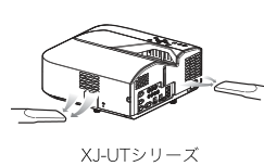
Diagram key
- Left nozzle and arrows: Carefully vacuum the first illustrated intake approximately monthly.
- Right nozzle and arrows: Carefully vacuum the second illustrated intake approximately monthly. Dust can overheat the interior and cause failure; clean dusty exhaust the same way.
正常時のインジケーター
Instructions from the manualInterpret normal indicator states8 steps
- Immediately after mains connection POWER is steady red and LIGHT/TEMP steady orange; wait until standby.
- Standby shows POWER steady red with LIGHT/TEMP off.
- UT312WN warm-up has POWER flashing green and LIGHT/TEMP steady orange.
- During network-system startup, POWER changes flashing-to-steady green while LIGHT/TEMP remain steady orange.
- Ready with Light Control On: POWER and LIGHT steady green, TEMP off.
- With Light Control Off: POWER steady green, LIGHT/TEMP off.
- Shutdown: POWER flashing red, LIGHT/TEMP off.
- Auto Projection Off makes POWER slowly flash green; the manual does not define other indicator states for that condition.
シリアルナンバーとboard no.の確認方法
Instructions from the manualFind the serial number and Board No.View
The serial number is on the bottom label. For Board No. press MENU, choose Information with Up/Down, read Board No., then MENU to close.
外部機器へのusb給電について
Instructions from the manualPower an external USB device9 steps
- UT312WN USB-A/DC5V supplies DC5V/1.5A; its separate USB-A supplies DC5V/0.5A.
- Before powering an external device, set normal Auto Power Off to Off.
- Shutdown, automatic restart or an error interrupts USB power and may erase unsaved data; save often.
- Use CASIO-verified equipment where available.
- Matching voltage/current alone does not guarantee all functions.
- Follow the external equipment’s connection instructions; incorrect battery connection can cause explosion, smoke or fire.
- CASIO disclaims external-device/data-loss responsibility.
- BLANK can suspend projection without stopping USB power.
- Auto Projection Off also maintains power until the projector turns off.
本機を天井から吊して設置する
Instructions from the manualCeiling-installation precautions8 steps
- The manual permits ceiling suspension upside-down or with the lens vertically downward.
- Ask the dealer for mounting details.
- Keep at least1m and as far as possible from fire detectors/alarms because hot exhaust can trigger them.
- Keep strong light off the remote receiver and test remote reception before mounting.
- Set Ceiling Projection On when upside-down.
- Use double-SEMS M4 screws with flat and spring washers.
- Overall screw length equals the washer thicknesses plus bracket thickness plus5–8mm thread engagement.
- Excess length can damage the projector; insufficient length fails to secure it.
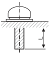
Diagram key
- Screw: M4 double-SEMS screw with a flat washer and spring washer.
- Bracket layer: Add bracket thickness and both washer thicknesses to engagement length for overall screw length.
- Engagement arrow (L in source text): Thread engagement5–8mm, shown by the complete two-ended arrow. Longer screws can damage the projector; shorter screws cannot secure it.
本機を壁に設置する(xj-utシリーズ)
Instructions from the manualWall-installation precautions5 steps
- Use the dedicated wall-mount bracket; the projector is upside-down.
- Ask the dealer for details.
- Keep as far as possible and at least1m from fire detectors/alarms to avoid exhaust-triggered activation.
- Avoid strong light near the receiver and test remote operation before mounting.
- Select Screen Settings > Ceiling Projection On for the inverted installation.
Monitor out端子の利用について(xj-utシリーズ、 xj-s400un、xj-s400wn)
Instructions from the manualUse MONITOR OUT and standby audio/video7 steps
- With power on, Computer1 sends COMPUTER IN1 to MONITOR OUT; Computer2 sends COMPUTER IN2.
- For Video, HDMI, CASIO USB Tools or Network, it continues the most recently selected Computer1/2 input.
- To output in standby choose Device Settings2 > Standby RGB/Audio > Output.
- Default is Do Not Output.
- Standby video is fixed to COMPUTER IN1; COMPUTER IN2 cannot be output in standby.
- Standby audio is the audio input assigned to Computer1 together with MIC.
- It goes through AUDIO OUT regardless of the normal Audio Output setting.
投映距離と投映サイズについて
Instructions from the manualProjection-distance and geometry reference4 steps
- The XJ-UT distances are approximate installation guides.
- Screen inches / diagonal centimetres / L centimetres / h centimetres: 50/127/6/24; 60/152/13/27; 80/203/27/32; 100/254/40/38; 110/279/47/40.
- L measures from the product front to the projection surface. h measures from the product bottom to the picture bottom.
- These endpoints differ from conventional F/S lens-centre geometry.
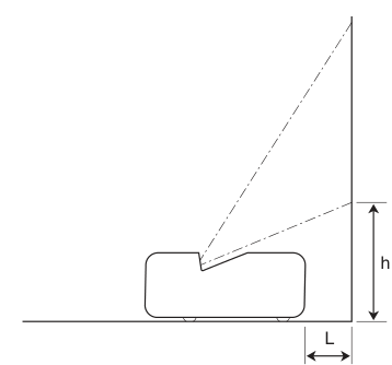
Diagram key
- h: Height from the product bottom to the picture bottom, shown by the full two-ended vertical arrow.
- L: Distance from the product front to the projection surface, shown by the full horizontal two-ended arrow. Approximate L/h cm:50in6/24; 60in13/27; 80in27/32; 100in40/38; 110in47/40.
対応信号一覧
Instructions from the manualSupported source timings7 steps
- Use the exact listed input timings.
- Native XJ-UT312WN projection remains1280×800.
- RGB(VESA): 640×480 at60/72/75/85Hz; 800×600 at56/60/72/75/85Hz; 1024×768 at60/70/75/85Hz; 1152×864/75Hz; 1280×720/60Hz; 1280×768/60Hz; 1280×800/60Hz; 1280×960/60Hz; 1280×1024/60/75/85Hz; 1366×768/60Hz; 1400×1050/60Hz; 1440×900/60Hz; 1600×1200/60Hz; 1680×1050/60Hz; 1920×1080/60Hz; 1920×1200RB/60Hz.
- Component HDTV: 1080p50/60, 720p50/60, 1080i50/60.
- Component SDTV: 576p50, 576i50, 480p60, 480i60.
- HDMI: 640×480/60, 800×600/60, 1024×768/60, 1280×720/60, 1280×768/60, 1280×800/60, 1280×960/60, 1280×1024/60, 1400×1050/60, 1920×1080/60, 1920×1200RB/60; SDTV480p, 576p; HDTV720p50/60, 1080i50/60, 1080p50/60.
- Composite video systems: NTSC, NTSC4.43, PAL, PAL-M, PAL-N, PAL60, SECAM.
プロジェクターのrs-232c制御について
Instructions from the manualRS-232C connection and command protocol10 steps
- Connect a computer to SERIAL using a commercial cross serial cable.
- Use19200bps, 8data bits, no parity, 1stop bit, no flow control.
- Commands use ASCII and decimal integers.
- Read format is (COMMAND?), returning (setting-range, current-value); write format is (COMMANDvalue).
- The printed example (VOL?) returns (0-30, 15); (VOL0) mutes.
- An unknown command returns ?; unsupported values are ignored.
- Wait for completion of each earlier command or body/remote-key action before sending another.
- While power is off send only PWR?, LMP? or PWR1.
- BLK and ARZ need a valid input signal.
- Only model-supported commands and values apply.
コマンド一覧
Instructions from the manualRS-232C picture, audio and power commands14 steps
- PWR0/1 Off/On.
- Applicable SRC values: 0RGB1, 1Component1, 2Video, 3RGB2, 4Component2, 6Auto1, 7HDMI, 8Network, 10Auto2, 13CASIO USB Tools, 15Templates.
- AIS: 1AUDIO IN1, 2AUDIO IN2, 3AUDIO IN R/L, 5HDMI audio, 8Network audio.
- The second HDMI values do not apply.
- BLK0/1 blank; VOL0–30(mute–maximum); VLP/VLM raise/lower by the supplied amount (e.g.VLP5/VLM5); MUT0/1 mute; PST1Graphics, 2Theater, 3Standard, 4Blackboard, 5Natural.
- Audio settings apply to the current source.
- ARZ0Standard for RGB/HDMI(PC), 2Standard for component/HDMI(DTV)/Video, 1=16: 9, 3Letterbox, 4Full, 5Real, 6=4: 3, 7=16: 10, restricted to that source’s supported choices.
- LMP reads cumulative light-use hours.
- PMD0Bright and1Normal apply with Light Control Off; 2enables brightness sensing; 3–9 select Light Control output7, 6, 5, 4, 3, 2, 1.
- FRZ0/1 Freeze.
- KST0–120 corresponds to GUI−60..60; KSP/KSM raise/lower by the supplied amount.
- HKS0–120 controls horizontal keystone (GUI−60..60); HKP/HKM raises/lowers it by the supplied amount.
- MIC0–3 adjusts microphone level.
- S-only colour modes do not apply.
RS-232C key, timer and status commands9 steps
- KEY performs the corresponding remote button, preserving its operation order: 1Up, 2Down, 3Left, 4Right, 5ENTER, 6ESC, 10FUNC, 11MENU, 12POWER, 13AUTO, 14INPUT, 15TIMER, 16ASPECT, 17BLANK, 18FREEZE, 19the printed light-control symbol, 20KEYSTONE+, 21KEYSTONE−, 22D-ZOOM+, 23D-ZOOM−, 24VOLUME+, 25VOLUME−, 31ID2, 32ID1, 33ID4, 34ID3.
- POS0top-up/front, 1top-down/rear, 2top-up/rear, 3top-down/front.
- APO0Off, 1=5min, 2=10min, 3=15min, 4=20min, 5=30min.
- STS is a serial-query result, not an invented display code: 0normal, 1fan, 2temperature, 7light, 16other fault.
- IDS0All, 1–4 matching IDs.
- ALC0/1 RGB1-level and AL2 0/1 RGB2-level adjustment; ASO0/1 Auto Projection Off disabled/enabled; ASS0/1 automatic input search Off/On.
- TIM0Presentation/1Countdown; TIT0–35999seconds(0h00m00s–9h59m59s).
- TMP is explicitly restricted to nonnetwork models and does not apply.
- MIR0/1 mirror; BSN reads Board No.
仕様
Instructions from the manualJapan XJ-UT312WN verified specifications11 steps
- Japan-domestic100V AC50/60Hz only; not for overseas use.
- Operate at5–35°C, 20–80%non-condensing humidity, 0–3000m altitude.
- Mono speaker16W.
- Single-chip DLP, WXGA0.65-inch1280×800, 16: 10, laser/LED, fixed zoom/manual focus, F2.3/f4.2.
- Screen50–110inches.
- Brightness3100lm and contrast20, 000: 1 under Light Control Off Bright/JIS measurement conditions.
- Native RGB1280×800; compressed RGB/HDMI up to1920×1200, component up to1920×1080.
- Horizontal15–91kHz, vertical50–85Hz; follow exact listed timings.
- Power160W at Light Control On output7, 90W at output1, 195W Off Bright, 170W Off Normal.
- Standby0.12W with Remote On disabled, 0.6W enabled.
- Approximately338×333×153mm including projections and5.8kg, excluding cable cover.
パソコンとプロジェクターを直接無線lan接続する
Instructions from the manualConnect a computer directly by wireless LAN6 steps
- With projector power off, connect the included YW-41 adapter to USB-A, then turn the projector on.
- Up to8computers/smart devices can connect wirelessly at once.
- Press INPUT, choose Network with INPUT or Up/Down, and ENTER to display network standby.
- Read its SSID and connect the computer’s wireless LAN to it.
- Standby displays OCC filename, projector name, IP address, login code when fixed/random is enabled, and SSID.
- With simultaneous wired/wireless operation, it shows LAN2 IP.
プロジェクターを既設ネットワークに有線lanで接続する
Instructions from the manualConnect wired LAN using DHCP3 steps
- Connect projector LAN to the existing network by cable.
- Press MENU > Network Settings > Wired LAN Information > ENTER.
- Check connection using projector name, MAC address, LAN1 IP, subnet, gateway and access-filter status.
Configure a fixed wired-LAN address8 steps
- Connect projector LAN to the existing network.
- Press MENU > Network Settings > Change Network Settings > ENTER.
- At IP Setting(LAN1), use Left/Right to select Manual.
- Enter IP address, subnet mask and default gateway.
- Choose Network Settings Update > ENTER, then Yes with Up/Down > ENTER.
- Wait for the network system to restart and show standby.
- Check Wired LAN Information.
- If DNS configuration is needed, use the Web Service settings procedure.
プロジェクターを既設の無線lanアクセスポイントに接続する
Instructions from the manualConnect to an existing wireless access point18 steps
- First connect the computer directly to the projector using the reviewed YW-41 procedure.
- Read projector IP on network standby.
- Open that IP in the computer browser to reach Web Service.
- Click Settings in the title bar.
- Log in using the Admin password(initially admin).
- Choose Wireless LAN Settings and enable Client Mode.
- Click Scan External Access Point.
- When scanning finishes, open the SSID dropdown and choose the desired access point.
- Alternatively enter an exactly known SSID directly.
- Choose the access point’s encryption method under Security and enter its password in Passphrase/WEP Key.
- For an existing fixed-IP network, click Save Changes, choose Later at the restart dialog, then open the lower Network Settings sidebar entry.
- Select LAN1 IP Setting and enter IP, subnet, gateway and DNS.
- Click Save Changes and Restart Now.
- Wait for restart; the direct computer/projector wireless connection is cut.
- Network standby reappears.
- Press MENU > Network Settings > Wireless LAN Information > ENTER.
- Confirm Operation Mode is Client Mode.
- This page reports projector/MAC, mode, IP, SSID/security in AP mode, and subnet/gateway in client mode.
プロジェクターをnatルーターとして使う
Instructions from the manualUse simultaneous wired and wireless LAN as a NAT router5 steps
- Follow direct YW-41 wireless setup, then connect projector LAN to the existing network using the reviewed DHCP or fixed-IP procedure.
- Up to8wireless clients can connect.
- Configure SSID/AP settings through Web Service if needed.
- By default, wireless clients can access the wired network.
- Access Filter can block it or select the manual’s HTTP-only mode; see the complete LAN2 setting reference.
プロジェクターの設定メニューでネットワーク設定を変更するには
Instructions from the manualChange network settings with the remote6 steps
- Display Network standby, press MENU > Network Settings > Change Network Settings > ENTER.
- Change the required settings: LAN1 Auto(default DHCP) or Manual(IP/subnet/gateway); wireless enabled(default)/disabled; Remote On disabled(default)/enabled; PJLink authentication enabled(default)/disabled.
- Wired/wireless information, Remote On and PJLink authentication are available only in the projector menu, not Web Service.
- Select Network Settings Update and ENTER.
- Choose Yes with Up/Down and ENTER.
- Wait for the network system to restart and show standby.
プロジェクターの設定メニューでネットワーク設定を初期化するには
Instructions from the manualReset network settings with the remote5 steps
- Display Network standby, press MENU > Network Settings > Change Network Settings > ENTER.
- Select Network Settings Reset > ENTER, then Yes with Up/Down > ENTER.
- The network system restarts and shows standby.
- This resets all Change Network Settings items and most Web Service settings.
- Projector Name, User List, Crestron Control and Firmware Update are retained.
Web serviceページのトップメニュー
Instructions from the manualOpen Web Service and inspect its menu5 steps
- When network-connected, read projector IP from network standby and enter it in the computer browser.
- A fixed-IP direct LAN connection also supports this method.
- If already connected in C-Connection, open its list, choose the connected-projector row and its Web Service control.
- The manufacturer notes that a browser security/privacy warning may appear while opening the projector’s own Web Service page; its instruction to proceed is scoped to that local projector page.
- Top menu: Settings opens detailed network setup; Language chooses display language; Moderator, Projector Remote andTemplate Customization are separate login entries; OCC downloads a connection file; C-Connection andMirrorOp Presenter links lead to connection software.
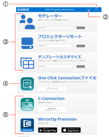
Diagram key
- 1: Settings opens detailed projector network configuration.
- 2: Language dropdown chooses the Web Service display language.
- 3: Login entries for Moderator, Projector Remote andTemplate Customization.
- 4: One Click Connection file download.
- 5: Download links for computer C-Connection andsmart-device MirrorOp Presenter.
プロジェクター設定ページにログインするには
Instructions from the manualLog in to projector Web Service settings4 steps
- Open the projector’s Web Service page and click title-bar Settings.
- Keep username admin unchanged, enter the Admin password(initially admin), and click Login.
- The settings page shows SSID(linking to wireless settings), projector name/IP and network-projection status.
- To return, click the title-bar menu control then Home.
プロジェクター設定を変更するには
Instructions from the manualSave or discard Web Service settings9 steps
- Log in to Settings and choose the page containing the required settings/information.
- Login Settings controls projection login codes; Network Settings contains wireless/IP; System Settings contains information, passwords and other settings; Update contains firmware and developer-only troubleshooting.
- Change settings.
- Discard Changes opens confirmation: Yes, refresh page cancels changes; No, cancel retains the unsaved edits.
- Click Save Changes to apply.
- If no restart is required, a confirmation appears.
- If required, choose Restart Now or Later.
- After Later, changes take effect at a later Save Changes > Restart Now, or when manually restarting the projector.
- To finish, open the title-bar menu and Home.
Web serviceページのパスワードを変更するには
Instructions from the manualChange Admin and moderator web passwords10 steps
- When networking the projector, change the initial web passwords.
- Log in to projector Settings, then choose System Settings > Change Password.
- For Admin, enter the old password(initially admin), then the new password twice.
- Admin is also the PJLink authentication password.
- For Moderator/Projector Remote/Template Password, enter the old password(initially moderator), then the new password twice.
- This password is shared by all three functions.
- Either or both password changes may be made as needed.
- Passwords require5–50characters: digits, upper/lowercase letters or single-byte symbols except yen/backslash, double quote and apostrophe.
- Characters are masked; the meter indicates strength.
- Click Save Changes.
ログイン設定
Instructions from the manualSet network login codes and connection-information display8 steps
- Login Code Option Disabled(default) requests no code.
- Random generates a new4-digit numeric code each time connected-user count reaches zero.
- Fixed requires a4-character code of digits or upper/lowercase letters.
- Connection Information Display Enabled(default) shows code, SSID, projector name/IP on connection, on projection start, or when Show Login Code is clicked.
- Disabled hides it.
- A disabled login code is not shown; SSID is not shown in client mode.
- Display Time is an integer in seconds up to300(default10).
- Zero suppresses the display even when display is enabled.
無線lan設定
Instructions from the manualConfigure access-point wireless settings13 steps
- Wireless LAN Enable toggles wireless(default enabled); disable for wired-only use or to stop radio transmission.
- Enable Access Point Mode(default) to accept client connections; this disables Client Mode.
- Default SSID is casiolpj000, where000is the last three wired-MAC characters.
- Set at most32characters using digits, upper/lowercase letters or single-byte symbols except yen/backslash, double quote and apostrophe.
- Shorten if it does not fit standby; blank cannot be saved.
- Mode B/G/N(default) selects802.11b/g/n automatically; B, G, N nominal maximums are11, 54, 300Mbps; actual throughput depends on environment.
- Channel width20MHz(default) or40MHz; B/G remain20MHz.
- Channel Auto(default) or1–11.
- Security NONE(default) gives no encryption; WPA-PSK orWPA2-PSK encrypts.
- Enter8–63characters containing at least two lowercase letters, two uppercase letters, two digits andtwo single-byte symbols; double quote/apostrophe are excluded.
- Default key is blank because security is NONE.
- SSID Broadcast enable(default) advertises the SSID; disabled hides it from client network lists.
- Save changes through the reviewed Web Service procedure.
クライアントモード
Instructions from the manualConfigure client-mode wireless security and EAP12 steps
- Enable Client Mode to join an external access point; this disables AP mode.
- Client mode is off by default.
- Choose the scanned SSID or enter it; default is blank.
- Security NONE(default) is for unencrypted networks.
- Otherwise match WEP, WPA-PSK AES/TKIP, WPA2-PSK AES/TKIP, orWPA/WPA2-EAP.
- EAP is selectable only with IO/USB firmware0.02.xx.xx.xx or later; check Information > Version > IO/USB.
- Enter the external access point password unless NONE.
- Hexadecimal WEP keys are unsupported.
- For WPA/WPA2-EAP, set EAP Type to match the RADIUS server: PEAP(default), TTLS orTLS.
- PEAP/TTLS: user name at most31single-byte alphanumeric characters, password at most64.
- TLS: user name if needed, max31; no password entry because only an unencrypted private key is supported.
- Register client andCA certificates as.pem, X.509v3, BASE64 text; private key as.key, RSA, BASE64, 2048bits.
ネットワーク設定
Instructions from the manualConfigure projector name and LAN1 addresses9 steps
- LAN1 addresses connect to an existing network through wired LAN or wireless client mode.
- LAN2 addresses serve clients of the projector’s AP mode.
- Default projector name casiolpj000uses last three wired-MAC characters.
- A replacement name allows at most16digits/upper/lowercase letters.
- LAN1 IP Setting unchecked(default) uses external DHCP and needs no manual values; the fields do not display assigned DHCP values.
- Checked uses fixed IP and requires IP, subnet, gateway andDNS.
- Defaults: 192.168.100.1, 255.255.255.0, 192.168.100.10, 192.168.100.10 respectively.
- Use dotted decimal.
- Do not add leading zeros to one/two-digit octets: 29cannot be029and5cannot be005.
Lan2側 ip設定
Instructions from the manualConfigure LAN2 addresses and access filtering8 steps
- LAN2 default AP address192.168.100.10; DHCP start192.168.100.11, end192.168.100.200; subnet255.255.255.0; DNS192.168.100.10.
- DHCP start/end must share the first three octets regardless of subnet mask.
- Do not add leading zeros.
- When used as NAT router, Access Filter Pass(default) permits wireless clients to access wired LAN/internet.
- Block prevents access to the wired side.
- Internet Only permits HTTP communication to the wired-side network including internet; do not infer that its name guarantees every local destination is blocked.
- System Information reports model string casiolpj, AP SSID(in AP mode), projector name, network firmware version, wired MAC andYW-41 wireless MAC.
- Without an adapter, the wireless MAC is shown as dashes.
その他設定
Instructions from the manualConfigure moderator thumbnails and Crestron control6 steps
- User List thumbnails are enabled by default.
- Disable to show device-type illustrations instead; user names always remain visible.
- Crestron Control requires controller IP(default blank), IP ID(default5) and port(default41794).
- ID/port permit single-byte digits only; IP uses dotted decimal without leading zeros.
- The Update page supplies firmware update access via official CASIO support.
- Troubleshoot functions are explicitly for developers only; no user remedy or extra update sequence is supplied here.
One click connectionファイルを作成する
Instructions from the manualPrepare C-Connection and download an OCC file8 steps
- Download the computer-appropriate C-Connection from CASIO support; check its current requirements, download/use conditions and installation instructions first.
- Chrome OS uses Chrome Web Store and lacks OCC support.
- Complete the projector’s network/name configuration before downloading OCC; the file records the name/IP at that time, and later network changes make an old file unusable.
- OCC is for C-Connection, not MirrorOp Presenter.
- Open projector Web Service and click Download under One Click Connection File to save the.occ file.
- Opening it launches C-Connection and, under default settings, begins projection.
- The installer andOCC can be copied/distributed to other computers for connection.
- If the browser cannot download OCC, try another browser.
プロジェクターのお気に入りリストを作成する
Instructions from the manualRegister or remove a favourite projector7 steps
- Start C-Connection.
- Search normally with the list-panel rescan control; for a projector on another subnet, use the reviewed manual name/IP search.
- Hover the required projector row and click its right-hand favourite star.
- The filled-star state confirms registration.
- To remove, open the favourites list, hover the projector row and click its right-hand filled star.
- Its row is removed.
- Chrome OS combines favourites with automatic results rather than offering a separate favourites-list display.
お気に入りデータをエクスポートするには
Instructions from the manualExport or import favourite-projector data6 steps
- Open C-Connection settings using the reviewed Windows/macOS procedure.
- On Favourites, click Export.
- Choose filename/location in the save dialog and Save; the format is.xml.
- To import, open the same tab and click Import.
- Select a favourites file exported from C-Connection and Open.
- Import replaces the current favourites list.
One click connectionで投映する
Instructions from the manualProject using One Click Connection6 steps
- Install C-Connection and connect the computer/projector network first.
- Obtain the target projector’s current OCC file from its administrator or Web Service.
- Chrome OS does not support OCC.
- Display network standby on the projector.
- Open the OCC file on the computer; C-Connection starts and default behaviour begins projection, showing its information panel.
- The Extended-tab OCC preference can instead connect and wait.
プロジェクターをリストから選んで投映する
Instructions from the manualProject from favourites or automatic search12 steps
- Display projector Network standby and start C-Connection.
- For favourites, open the favourites list(created/imported beforehand); for automatic search, use the startup search results.
- Automatic search finds only the same subnet.
- Hover the required projector row and click Connect.
- If a login-code dialog appears, enter the code shown on network standby.
- The connected row gains a check mark and projector name appears at the window top.
- The list changes to information panel, then mini panel after inactivity.
- Click Play to start projecting the computer screen.
- Click Pause to hold the current image until Play or Stop.
- Chrome OS prompts for the sharing target after Play; choose it and Share.
- Click Stop to end projection while retaining connection; Play resumes.
- Close C-Connection with its upper-rightX to disconnect.
プロジェクターを手動で検索する
Instructions from the manualSearch for a projector manually8 steps
- If automatic search does not find it, display Network standby and start C-Connection.
- Click the bottom field labelled to enter an IP address or projector name.
- Read the name/IP from standby and enter it, then Connect.
- Chrome OS accepts only IP.
- This method can find a different subnet.
- After connection, use the reviewed login-code, Play, Pause, Stop anddisconnect controls.
- If name search fails, an incorrect projector DNS address is possible; contact the network administrator.
- Save the found projector as a favourite to simplify future use.
複数パソコンから1台のプロジェクターへの同時投映について
Instructions from the manualManage simultaneous projections and layouts6 steps
- Up to4computers project at once.
- WXGA Auto Layout uses one full image, two side-by-side, three orfour in the shown2×2layout.
- XGA’s vertically stacked two-image variant does not apply to UT312WN.
- Full Screen displays only the computer choosing it, even during multiple projection.
- Switch back to Auto Layout to restore multiple images.
- If four are already projecting, stop one before another computer starts.
C-connectionウィンドウの表示とボタン
Instructions from the manualUse C-Connection panels and playback controls11 steps
- Ordinary startup shows the full list panel.
- After connection, inactivity automatically reduces it to information then mini panel.
- List panels select projectors; information/mini panels control current projection.
- The gear opens Windows Settings, Disconnect, Information andExit; on Chrome OS it opens Settings. macOS uses its menu bar.
- Full-list down triangle switches to mini panel, and up triangle to information.
- Mini-list arrows switch to full list or mini panel.
- List-panel ellipsis shows found/favourite projectors; star shows favourites; rescan refreshes the network; search filters displayed names; X exits.
- Information-panel gear matches full-list gear; down triangle switches to mini panel, and up triangle to full list.
- Mini-panel up triangle opens information, and down triangle opens mini list.
- In information/mini panels, the layout button switches Full Screen/Auto Layout; Play starts, Stop ends projection, Pause holds a still image, and speaker toggles network audio/mute.
- X exits.
C-connectionメニューバー(macos)
Instructions from the manualC-connection設定項目一覧
Instructions from the manualChange C-Connection settings and respect Chrome OS limits14 steps
- Open C-Connection; settings can change without network connection.
- On Windows, show information/full-list panel, click gear > Settings.
- On macOS, use C-Connection > Settings/Preferences.
- Change tabs, then upper-rightX applies all changes.
- General: username(max20characters, default computer login name); Enable Receiver Operation(default off, requires a chosen4-digit numeric passcode for PC Remote); Mute PC Audio During Projection(Windows only, default off); Always On Top(default off, may not override full-screen apps).
- Favourites: Default List Automatic Search(default) orFavourites, andXML import/export.
- Extended: Duplicate(default main display) orExtended(requires commercially available display emulator); OCC Project(default) orConnect-and-wait; Reset restores Extended settings.
- Hotkeys default enabled.
- Windows Ctrl+Shift ormacOS Control+Command plusP=play/pause, S=stop, E=main/extended, M=mute, A=Full Screen/Auto Layout.
- Reset restores hotkeys except Enabled.
- Information shows version/copyright.
- Chrome OS lacks OCC, separate favourites display, name search, hotkeys, PC Remote, Extended/Hotkey tabs, andGeneral Mute PC Audio/Always On Top.
- General username andreceiver-operation setting, Favourites Default List andfavourites data, andInformation remain available as printed.
- Favourites appear together in auto results.
モデレーター機能の利用
Instructions from the manualModerate projection from a computer16 steps
- Existing wired network supports up to40connected terminals.
- In NAT mode, the wired allowance is40minus wireless clients(e.g.5wireless permits35wired); only4can project simultaneously.
- Open Web Service and log in at Moderator with its password(initially moderator).
- Connected user names appear.
- Optionally check Prohibit Other Users’ Projection Operations.
- Then only this page can start projection/change layout; clients may still stop ordisconnect.
- Unchecked permits all client operations.
- Find the required user row.
- Its Auto Layout Play button starts in Auto Layout; Full Screen Play starts full-screen; Stop stops that user; the corresponding layout buttons switch layouts; disconnect cuts its connection.
- Global Stop All andDisconnect All affect every terminal.
- Stop one of four before starting another.
- Show Login Code displays it beside the button and projects connection information; disabled code appears as a dash.
- User list updates on connect/disconnect or browser refresh.
- Click Logout when finished.
- Logging out/closing the page restores client operations even if prohibition remains checked; next login retains the checkmark.
- Change this shared password through System Settings > Change Password.
リモコンを使って複数端末からの投映をコントロールするには
Instructions from the manualModerate projection with the remote7 steps
- During Network standby orprojection, press ESC to open the user list(up to12terminals perpage).
- Thumbnails/user names follow connection order: left-to-right across successive rows.
- Play/Stop symbols show projection state.
- Move focus with cursor keys, then ENTER toggles that terminal’s projecting/stopped state.
- Repeat as needed; up to4can project.
- Press ESC to close the user list andstart the selected terminals.
- If all are stopped, the Network standby screen appears.
プロジェクターリモート
Instructions from the manualControl the projector from Web Service4 steps
- Open Web Service, enter the Projector Remote password(initially moderator), andLogin.
- Use the displayed remote buttons to operate the projector.
- The window’s power button cannot turn the projector on.
- Click title-bar Logout to return to Home.
スマートデバイスからパソコンをリモート操作する
Instructions from the manualStart PC Remote from Android or iOS14 steps
- Install MirrorOp Receiver on the smart device as named by this guide.
- PC Remote requires the projecting computer, smart device andprojector on the same subnet(the guide specifies matching first three IPv4octets).
- Chrome OS C-Connection does not support PC Remote.
- Start computer network projection with C-Connection.
- Open its settings > General andenable receiver operation.
- Choose a4-digit numeric passcode andclose settings.
- This persists until changed.
- Android: start MirrorOp Receiver, open its upper-right menu > Settings, enable Search for senders on start, quit andrestart the app.
- Select the required computer andenter the computer’s chosen passcode. iOS: quit MirrorOp Receiver if running.
- In iOS Settings > Receiver, enable Search for senders on start.
- Start MirrorOp Receiver, select the computer, andenter its chosen passcode.
- The device settings persist until changed.
- To finish, quit MirrorOp Receiver.
- Turning off the projector orquitting C-Connection also ends PC Remote.
テンプレートカスタマイズ
Instructions from the manualAdd,replace ordelete custom template images11 steps
- Do not register personal information such as name, address, phone orbirth date: unauthorized access, theft ordisposal could expose it.
- Up to81additional JPGtemplates, max4096×2160pixels, are supported; up to9perfolder.
- Built-in templates cannot be changed/deleted.
- Open Web Service andlog in at Template Customization with its password(initially moderator).
- Click the required folder.
- First built-in folder is view-only; it cannot register, change ordelete.
- To add, click Select Image, choose the JPGandOpen.
- To delete, hover the image, click trash, andconfirm Yes, delete template.
- To replace, hover the target image, click Change Image, andchoose/Open the replacement.
- Click Save Changes in the template editor.
- Click back to return to folders, then title-bar Logout to return Home.
フォルダー名を変更するには
Instructions from the manualRename a custom-template folder4 steps
- Log in to Template Customization.
- Click the target folder-name box andenter a new name that fits comfortably; overlong names may be clipped on projector template selection.
- Click Save Changes.
- To cancel, log out without saving.
外部ネットワーク機器からのプロジェクター制御
Instructions from the manualUse external network control and check firewall ports8 steps
- The guide supports all PJLink Class1version1.00commands, Crestron controllers/RoomView Express, andAMX Device Discovery.
- Consult CASIO’s LAN support for details.
- PJLink authentication uses the projector Admin password.
- If needed, check network/personal firewalls against the actual source table.
- Network projection: TCP1234, UDP5353, 54022, 1900.
- PC Remote: TCP389, 3268, 515, 8080, 18765; UDP1900, 18676.
- PJLink usesTCP4352for control andUDP4352for discovery.
- No other port association is inferred.
はじめに
Instructions from the manualFlash Loader requirements2 steps
- Use the exact projector model’s CASIO download, the USB driver, Flash Loader, a USB cable and the model-specific .cpr file.
- Use a PC/AT-compatible computer with preinstalled Windows10/8.1/8/7SP1, PentiumM1.6GHz or faster and the OS-recommended CPU/memory, 1024×768-or-higher full-colour display, keyboard and pointing device.
LOGO Loader requirements2 steps
- Use the exact projector model’s CASIO download, the USB driver, LOGO Loader, a USB cable and the model-specific .cph file.
- Use a PC/AT-compatible computer with preinstalled Windows10/8.1/8/7SP1, PentiumM1.6GHz or faster and the OS-recommended CPU/memory, 1024×768-or-higher full-colour display, keyboard and pointing device.
公開されているファームウェアデータがプロジェクターのファームウェアより新しいか確 認するには
Instructions from the manualCheck for newer firmware3 steps
- Check the official CASIO support download for firmware for the exact model.
- While projecting press MENU, use Up/Down to select Information and compare the displayed Version with the download.
- Update only if the download is newer.
Usbドライバーをインストールするには
Instructions from the manualFlash Loader USB-driver installation4 steps
- Install the USB driver BEFORE connecting the computer and projector.
- If already connected, unplug USB, install the driver, then reconnect.
- Download CASIO USB Driver.
- Double-click PjUsbDriverSetup_EN.exe, follow its dialogs; on Windows7/8/8.1 accept User Account Control with Yes.
LOGO Loader USB-driver installation4 steps
- Install the USB driver BEFORE connecting the computer and projector.
- If already connected, unplug USB, install the driver, then reconnect.
- Download CASIO USB Driver.
- Double-click PjUsbDriverSetup_EN.exe, follow its dialogs; on Windows7/8/8.1 accept User Account Control with Yes.
プロジェクターのファームウェアを更新するには
Instructions from the manualTransfer a firmware update13 steps
- Download CASIO Projector Flash Loader and the correct model’s firmware .cpr ZIP; extract files into the same folder.
- Unplug the projector mains cord.
- Connect computer USB to projector LOGO Micro-USB TypeB.
- Reconnect the projector mains cord and turn on.
- POWER flashes orange with approximately1second on/1second off.
- Close all running computer applications.
- Run PjFlashLoader_EN.exe.
- Click Choose, select the .cpr file and Open.
- Click Upload.
- During transfer POWER goes out and the loader shows progress.
- NEVER turn off either device or disconnect USB during transfer.
- After completion POWER flashes orange again and a dialog appears.
- Click OK, close the loader with X, disconnect USB from both devices, then unplug the projector power cord.
ユーザーロゴ用の画像ファイルについて
Instructions from the manualChoose a supported logo image5 steps
- Use a BMP with RGB24-bit full colour, minimum640×480 and maximum1280×800 pixels.
- For XJ-UT312WN the recommended image is its native1280×800.
- The logo may be selected for Blank or No Signal screens on UT312WN.
- The generic guide also mentions startup screens, but use depends on the model; this model’s main manual supplies no startup-screen menu.
- Transfer deletes the previous user logo.
プロジェクターにユーザーロゴを転送するには
Instructions from the manualTransfer a user logo16 steps
- Download CASIO Projector LOGO Loader and the exact model’s .cph header ZIP; extract them to the same folder and place the supported BMP there.
- The transfer deletes the previous logo.
- Unplug the projector mains cord if connected.
- Connect computer USB to LOGO Micro-USB TypeB.
- Reconnect mains and turn on; POWER flashes orange approximately1second on/1second off.
- Close all computer applications.
- Run PjLogoLoader_EN.exe.
- Click the upper Choose, select the correct .cph and Open.
- Check LOGO Header File says Format OK.
- If not, use the correct-model header or redownload a possibly corrupt header and choose it again.
- Click the lower Choose, select the BMP and Open.
- Check Image File says Format OK; otherwise use the specified format and dimensions.
- Click Upload.
- During transfer POWER goes out and progress is displayed; NEVER turn off either device or disconnect USB.
- On completion POWER flashes orange and a dialog appears.
- Click OK, close the loader with X, disconnect USB from both devices, then unplug projector mains.
Controls and parts
See the manual diagrams 2 diagrams
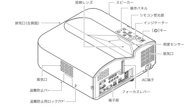
Diagram key
- Projection lens: Projects the image; do not touch orlook into the illuminated lens.
- Speaker: Built-in speaker.
- Control panel: Body operating keys.
- Remote receiver: Receives the remote signal.
- Indicators: POWER/STANDBY, LIGHT andTEMP show state.
- Power key: Turns power on oroff.
- Illuminance sensor: Measures ambient brightness for enabled Light Control sensing.
- Intake(right callout): Right-side illustrated intake; keep clear.
- AC inlet: Supplied mains cord connection.
- Focus lever: Slide up/down to focus.
- Terminal area: External connections.
- Security lock hole: Attach an anti-theft chain/lock; source footnote names Kensington-compatible equipment.
- Security bar: Theft-prevention bar.
- Intake(left-front callout): Left-front illustrated intake; keep clear.
- Exhaust(left side): Hot exhaust opening; keep clear.
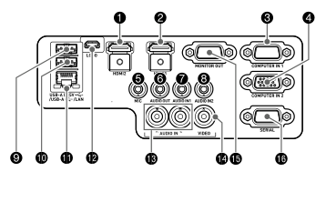
Diagram key
- 1: HDMI2; UT352W/UT352WN only, absent on UT312WN.
- 2: HDMI input on UT312WN; called HDMI1 on UT352W/UT352WN.
- 3: COMPUTER IN1.
- 4: COMPUTER IN2.
- 5: MIC, dynamic microphone input.
- 6: AUDIO OUT.
- 7: AUDIO IN1.
- 8: AUDIO IN2.
- 9: USB-A/DC5V, USB host and5V/1.5A supply on UT312WN.
- 10: USB-A, USB host and5V/0.5A supply on UT312WN.
- 11: LAN, RJ-45 network connection.
- 12: LOGO, Micro-USB TypeB service connection.
- 13: AUDIO IN R/L.
- 14: VIDEO, composite input.
- 15: MONITOR OUT.
- 16: SERIAL, RS-232C.
Model details
Model and compatibility
- Native resolution
- WXGA1280×800,16:10,0.65-inch DLP. [1]
- Power supply
- 100V AC50/60Hz;Japan only. [1]
- Environment
- 5–35°C;20–80%non-condensing humidity;0–3000m altitude. [1]
- Brightness and lens
- 3100lm under stated JIS conditions;fixed zoom,manual focus,F2.3/f4.2. [1]
- Size and mass
- Approximately338×333×153mm including projections;5.8kg,excluding cable cover. [1]
- Speaker
- 16W mono. [1]
- Connections
- One HDMI;COMPUTER IN1/2;MIC;USB-A/DC5V;USB-A;LAN;LOGO;AUDIO OUT;AUDIO IN1/2;AUDIO IN R/L;VIDEO;MONITOR OUT;SERIAL. [1]
- USB power
- USB-A/DC5V5V1.5A;USB-A5V0.5A. [1]
- Included wireless adapter
- YW-41 supplied with XJ-UT312WN;2.4GHz wireless networking. [1]