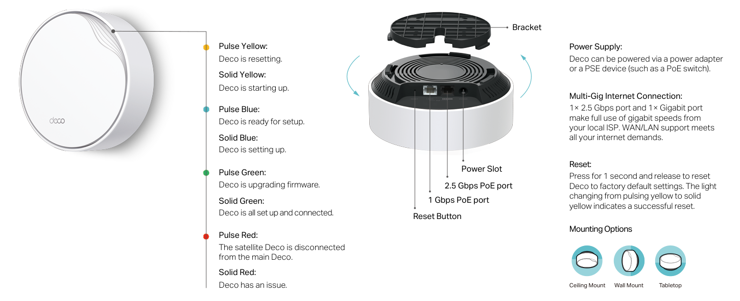
2.5 Gbps PoE port: 2.5 Gbps Ethernet port with PoE.
1 Gbps PoE port: Gigabit Ethernet port with PoE.
Reset Button: Reset control on the underside.
Power Supply: Use a power adapter or a PSE device such as a PoE switch.
Multi-Gig Internet Connection: One 2.5 Gbps and one Gigabit port; both support WAN/LAN operation.
Reset: Press for 1 second and release to restore factory defaults. Pulsing yellow changing to solid yellow indicates successful reset.
Ceiling Mount: Ceiling mounting option.
Wall Mount: Wall mounting option.
Tabletop: Tabletop placement option.
Curved bracket arrows: Bracket attachment/rotation is shown; follow the applicable mounting procedure and its clockwise locking instruction.
Message or indicatorWhat it meansCheck or action
Pulse Yellowpulse Yellow — Deco is resetting
Deco is resetting.
Solid Yellowsolid Yellow — Deco is starting up
Deco is starting up.
Pulse Bluepulse Blue — Deco is ready for setup
Deco is ready for setup.
Solid Bluesolid Blue — Deco is setting up
Deco is setting up.
Pulse Greenpulse Green — Deco is upgrading firmware
Deco is upgrading firmware.
Solid Greensolid Green — Deco is all set up and connected
Deco is all set up and connected.
Pulse Redpulse Red — The satellite Deco is disconnected from the main Deco
The satellite Deco is disconnected from the main Deco.
Solid Redsolid Red — Deco has an issue
Deco has an issue.
Troubleshooting
Find the problem you are experiencing
Main Deco setup: We couldn’t find Deco1 check
Main Deco setup: We couldn’t find Deco
Use TP-Link FAQ 2239 or its main-Deco discovery video, as linked from the official user guide. If the problem persists, contact TP-Link support.
Satellite setup: We couldn’t find another Deco1 check
Satellite setup: We couldn’t find another Deco
Use TP-Link FAQ 1447 or its satellite-Deco discovery video, as linked from the official user guide. If the problem persists, contact TP-Link support.
Setup stuck on Testing Internet Connection1 check
Setup stuck on Testing Internet Connection
Use TP-Link’s Testing Internet Connection video linked from the official user guide. If the problem persists, contact TP-Link support.
Wireless devices cannot connect to Deco1 check
Wireless devices cannot connect to Deco
Use TP-Link FAQ 2718, linked from the official user guide. If the problem persists, contact TP-Link support.
Deco suddenly loses internet access1 check
Deco suddenly loses internet access
Use TP-Link FAQ 1454, linked from the official user guide. If the problem persists, contact TP-Link support.
Finding a suitable spot for Deco1 check
Finding a suitable spot for Deco
Use TP-Link FAQ 1446, linked from the official user guide. If the problem persists, contact TP-Link support.
Deco app does not work properly1 check
Deco app does not work properly
Use TP-Link FAQ 1456, linked from the official user guide. If the problem persists, contact TP-Link support.
Forgotten TP-Link ID login password1 check
Forgotten login password
Tap Forgot Password and follow the app to reset the login password.
Harmful radio or television interference4 checks
If radio/TV interference is confirmed by turning the equipment off and on, try one or more of these measures.
Reorient or relocate the receiving antenna.
If radio/TV interference is confirmed by turning the equipment off and on, try one or more of these measures.
Increase the separation between the equipment and receiver.
If radio/TV interference is confirmed by turning the equipment off and on, try one or more of these measures.
Connect the equipment to an outlet on a different circuit from the receiver.
If radio/TV interference is confirmed by turning the equipment off and on, try one or more of these measures.
Consult the dealer or an experienced radio/TV technician for help.
Guides
Appearance
Instructions from the manual
Reset Deco to factory defaultsView
Press Reset for 1 second and release it to restore factory defaults. A change from pulsing yellow to solid yellow indicates a successful reset.
Power up your deco
Instructions from the manual
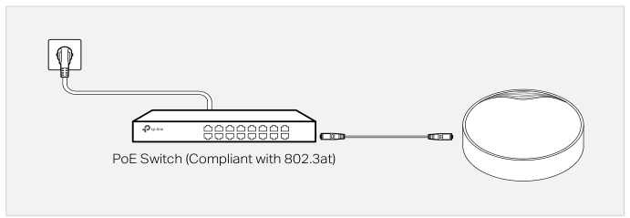
Power Deco through an 802.3at PoE switch3 steps
Use a PSE device, such as a PoE switch, that complies with Power Source Class 2 (PS2) or Limited Power Source (LPS), and Electrical Energy Source Class 1 (ES1), of IEC 62368-1.
Connect an Ethernet cable from an 802.3at-compliant PoE switch to Deco’s Ethernet port.
The power must be at least 18 W.
PoE power connection. Use an 802.3at switch providing at least 18 W and meeting PS2/LPS and ES1 requirements.
Diagram key
PoE Switch (Compliant with 802.3at): Connect an 802.3at-compliant PoE switch; power must be at least 18 W.
Ethernet connection: Run the Ethernet cable from the PoE switch to Deco’s Ethernet port.
Deco: Deco receives power through its Ethernet connection.
Power Deco with the supplied adapterView
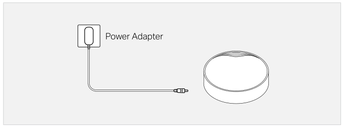
Connect one end of the provided power adapter to Deco’s power port and the other end to a standard electrical wall outlet.
Power connection with the supplied adapter.
Diagram key
Power Adapter: Use the provided power adapter in a standard wall outlet.
Adapter cable: Connect the other end to Deco’s power port.
Deco: Deco is powered through its power port.
Set up your deco network
Instructions from the manual
Set up the Deco network17 steps
Download and install TP-Link Deco from Google Play or the App Store, or scan the manual’s QR code.
Use an iOS or Android device.
Open the app and log in with your TP-Link ID; create an ID first if you do not have one.
If you forget your login password, tap Forgot Password and follow the app.
Search for and select your Deco model.
If you have multiple Deco models, tap the question below the search box to check how to maximize the overall network.
Power off your modem, connect Deco to it, then power both on.
Without a modem, connect Deco directly to the Ethernet outlet.
The illustrated PoE setup screen says not to mount Deco until setup is finished.
Select or customize a location for Deco.
The location becomes its name.
Choose the internet connection type and enter its information.
If unsure, contact your internet service provider.
Create a Wi-Fi network name and password, then connect to it.
The illustrated app requires at least 8 characters and recommends a combination of letters, numbers and symbols.
When setup is complete, connect your devices to the Deco network.
If you have more Decos, tap Add another Deco to add them.
Mount your deco
Instructions from the manual
Choose the mounting holes and screws4 steps
Choose the mounting method for your wall, ceiling or junction box using the supplied screws.
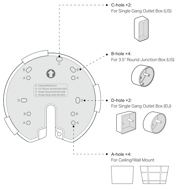
Use the four A-holes for ceiling/wall mounting.
The two C-holes are for a US single-gang outlet box; four B-holes are for a US 3.5-inch round junction box; the two D-holes are for an EU single-gang outlet box.
The printed screw key specifies M3.5×28 for the US outlet-box option; M3×28 or M3.5×28 for the EU option; ST3.5×30 for wall mounting; and M3×30 for ceiling mounting.
Mounting-bracket hole choices. US/EU variants and all repeated letter markings are explained below; screw size choices remain in the instructions.
Diagram key
C-hole×2: US single-gang outlet box.
B-hole×4: US 3.5-inch round junction box.
D-hole×2: EU single-gang outlet box.
A-hole×4: Ceiling/wall mounting.
Bracket orientation arrow: Bracket orientation shown by the manufacturer; follow the matching mounting illustration and LED orientation.
Option 1: on the wall/ceiling
Instructions from the manual
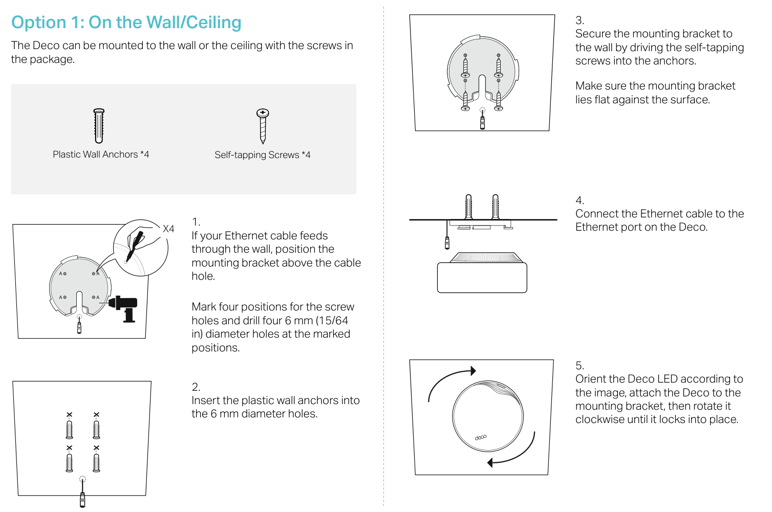
Mount Deco on a wall or ceiling8 steps
If the Ethernet cable feeds through the wall, position the mounting bracket above the cable hole.
Mark four screw positions and drill four 6 mm (15/64 in) diameter holes.
Insert the plastic wall anchors into the 6 mm holes.
Drive the self-tapping screws into the anchors to secure the bracket.
Make sure it lies flat against the surface.
The manual specifies four anchors and four self-tapping screws.
Connect the Ethernet cable to Deco’s Ethernet port.
Orient the Deco LED as shown in the reviewed figure, attach Deco to the bracket and rotate it clockwise until it locks in place.
Wall/ceiling mounting sequence, all five steps and complete hardware/marking key.
Diagram key
Plastic Wall Anchors×4: Four plastic anchors.
Self-tapping Screws×4: Four self-tapping screws.
1 / X4 / drilling arrow: For an in-wall cable, position the bracket above the cable hole; mark and drill four 6 mm (15/64 in) holes.
2 / anchors: Insert anchors into the 6 mm holes.
3 / screw arrows: Secure the bracket by driving the screws into the anchors; keep the bracket flat.
4 / Ethernet connection: Connect Ethernet to Deco.
5 / clockwise arrows: Orient the LED as illustrated, attach Deco and rotate clockwise until locked.
A markings (repeated): Four ceiling/wall mounting holes.
Option 2: on a wall junction box
Instructions from the manual
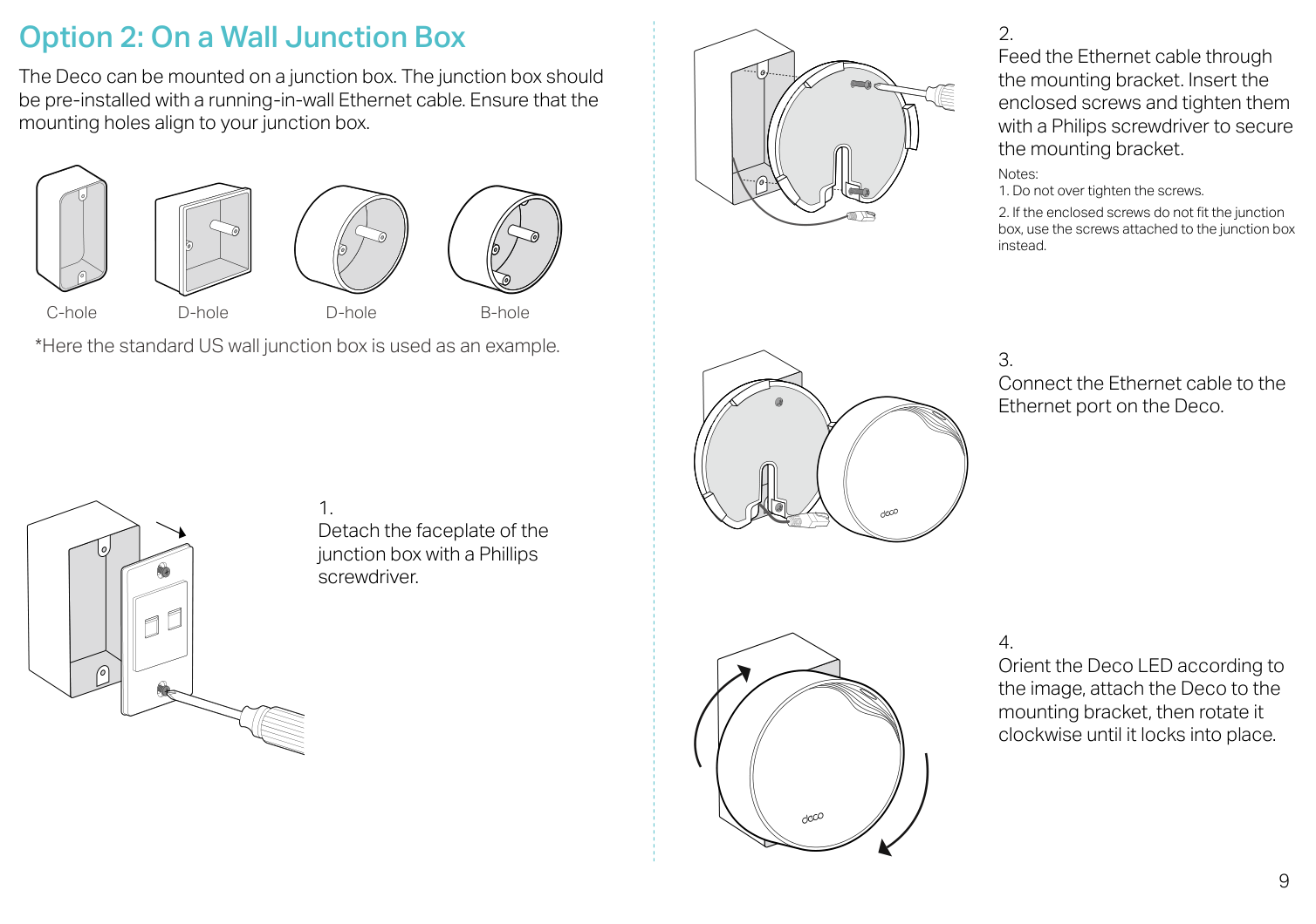
Mount Deco on a wall junction box10 steps
Use a junction box with a pre-installed in-wall Ethernet cable.
Ensure its mounting holes align with the bracket.
The illustration uses a standard US wall junction box as an example.
Detach the junction-box faceplate with a Phillips screwdriver.
Feed the Ethernet cable through the bracket.
Insert the enclosed screws and tighten them with a Phillips screwdriver to secure the bracket.
Do not overtighten.
If the enclosed screws do not fit the junction box, use the screws supplied with that box instead.
Connect the Ethernet cable to Deco’s Ethernet port.
Orient the Deco LED as shown in the reviewed figure, attach Deco to the bracket and rotate it clockwise until it locks in place.
Junction-box mounting: complete four-step sequence. The US wall box is an example; retain EU/US hole choices.
Diagram key
C-hole: US single-gang box.
D-hole (rectangular box): EU single-gang box option shown.
D-hole (round box): Alternative EU box shape shown under the D-hole label.
B-hole: US 3.5-inch round box.
1 / faceplate arrows: Use a pre-installed in-wall Ethernet cable and aligned holes. Remove the faceplate with a Phillips screwdriver.
2 / bracket screws: Feed Ethernet through the bracket and tighten enclosed screws with a Phillips screwdriver; do not overtighten. If they do not fit, use the box screws instead.
3 / Ethernet connection: Connect Ethernet to Deco.
4 / clockwise arrows: Orient the LED as shown, attach Deco and rotate clockwise until locked.
Option 3: in a ceiling tile
Instructions from the manual
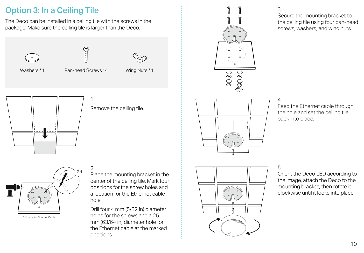
Mount Deco in a ceiling tile9 steps
Use a ceiling tile larger than Deco.
The procedure uses four wing nuts, four washers and four pan-head screws.
Remove the ceiling tile.
Place the bracket at the center of the tile.
Mark four screw-hole positions and one Ethernet-cable-hole position.
Drill four 4 mm (5/32 in) screw holes and a 25 mm (63/64 in) Ethernet cable hole.
Secure the bracket to the tile with four pan-head screws, washers and wing nuts.
Feed the Ethernet cable through the hole and put the ceiling tile back into place.
Orient the Deco LED as shown in the reviewed figure, attach Deco to the bracket and rotate it clockwise until it locks in place.
Ceiling-tile mounting: complete five-step sequence, all hardware and hole sizes. Use a tile larger than Deco.
Diagram key
Washers×4: Four washers.
Pan-head Screws×4: Four pan-head screws.
Wing Nuts×4: Four wing nuts.
1 / tile removal arrow: Remove a ceiling tile larger than Deco.
2 / X4 / Drill Hole for Ethernet Cable: Center the bracket, mark four screw holes and a cable hole. Drill four 4 mm (5/32 in) screw holes and a 25 mm (63/64 in) Ethernet hole.
3 / fastener stack: Fasten the bracket with four pan-head screws, washers and wing nuts as shown.
4 / cable arrow: Feed Ethernet through the hole and replace the ceiling tile.
5 / clockwise arrows: Orient the LED as shown, attach Deco and rotate clockwise until locked.
A markings (repeated): Four ceiling/wall mounting holes.
Safety information
Instructions from the manual
Safe operation and when to contact service12 steps
Keep Deco away from water, fire, humidity and hot environments.
Do not disassemble, repair or modify the device.
Contact TP-Link if service is needed.
Do not use damaged chargers or USB cables, or chargers other than those recommended.
Keep the adapter near the equipment and easily accessible.
Do not use the device where wireless devices are prohibited.
Keep Deco and its power adapter more than 15 cm (6 inches) from pacemakers and other implanted medical devices.
If interference is suspected, turn off Deco and consult your physician for advice specific to the implanted device.
Use only the manufacturer’s power supplies provided in the original package.
Contact TP-Link with questions.
Operate at 0–40°C (32–104°F).
Read and follow the safety information; use the product carefully because improper use can cause accidents or damage.
安全諮詢及注意事項
Instructions from the manual
Cleaning, ventilation and service precautions9 steps
Use the power type marked on the product.
Disconnect the power before cleaning.
Do not use liquids, spray cleaners or a wet cloth.
Keep moisture and other liquids away from the device.
Do not block or cover its ventilation slots and openings; they prevent overheating and keep operation reliable.
Keep it away from heat sources.
Do not put it in an enclosed space without proper ventilation.
Do not open the housing or repair it yourself.
Contact the manufacturer or its agent if it malfunctions.
National restrictions
Instructions from the manual
Use Deco indoors in the UK and EUView
Use Deco indoors only in Great Britain, all EU member states, EFTA countries and Northern Ireland.
Rf exposure information
Instructions from the manual
Maintain the RF exposure distanceView
Use Deco at least 20 cm from your body. The FCC statement also requires at least 20 cm from all people and prohibits co-location or operation with another antenna or transmitter.
Getting started
Instructions from the manual
Stay online during app download and loginView
Remain online using Wi-Fi or mobile data while downloading the app and logging in. Download TP-Link Deco for iOS or Android and follow the app through setup.
For indoor decos:
Instructions from the manual
Follow the quick guide’s indoor power precautions9 steps
For this indoor Deco, keep it away from fire and hot environments.
Do not disassemble, repair or modify it; contact TP-Link for service.
Do not use it where wireless devices are prohibited.
Do not use damaged chargers or USB cables, or chargers other than those recommended.
Keep the power adapter or power-supply-cord plug near the equipment and easily accessible.
Use only manufacturer-supplied power supplies in the original package; consult the model user manual for applicable power supplies and contact TP-Link with questions.
For products powered by a power-supply cord with a three-pin plug, connect the product to an earthed wall outlet.
This condition does not prescribe a different adapter for the model.
Read and follow the safety information and use the product carefully; improper use may cause accidents or damage.
Model details
Model and compatibility
Ports and controls
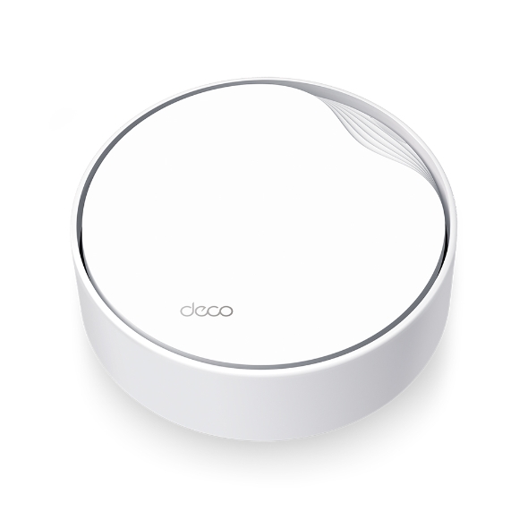
Deco X50-PoE has a 2.5 Gbps PoE port, a Gigabit PoE port, a power socket, a Reset button and a status LED. Both Ethernet ports support WAN/LAN operation.
Power
Use the supplied power adapter or an 802.3at PoE switch providing at least 18 W. The PSE must meet the manual’s PS2/LPS and ES1 requirements.